Have you ever asked yourself what the most valuable thing is in your life? If you think long and hard, most people will narrow it down to “time”. What would you do if you had more time? Perhaps you would spend it with your family or friends. Professionally you might use it to come up with new ideas or work on a new project. Unfortunately, we have not found a way to create additional time, but we can reduce the time spent on the things we do daily.
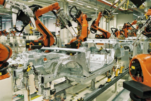
For the sake of this article, let’s look at design and manufacturing. For hundreds of years, we have seen various industries find innovative ways to save time by automating current processes. In some cases, automation not only impacts the company, but it may also even have a nationwide or global effect as we have seen early in the automotive industry. That’s a big example, but many times even very small changes in the way we do things can have a significant impact on an individual and sometimes the entire organization.
If you or your company uses Autodesk Inventor, I want you to think about something as you continue through this article. Ask yourself, “Where am I at on the automation spectrum?” Everyone who uses Inventor is automating at some capacity. Look at the following diagram. These are some of the steps you will take in Inventor as you grow in your automation maturity.
![]()
Parametric Modeling
As you model your designs in Inventor, you are adding your design intent and knowledge into the file. The beauty of that 3D part file is the information that stays with it. The dimensions, formulas, and constraints are maintained so that anyone can open it and make changes when needed. When that change is made, the model will behave as expected based on your design intent.
![]()
Specialized Tools
Autodesk Inventor wants you to be a great designer by providing specialized tools for the parts you make. The last thing you want to do is figure out how to draw something in 3D. Let the software do the modeling work for you. Examples of this are sheet metal, weld frames, tube and pipe, and plastic parts. Inventor is going to help you create the model while you specify the features that you need in your design.
![]()
New Product Configurations
Do you have products that are similar but contain different features and sizes? You now have this great design that contains all the design intent and knowledge you applied. By using iLogic, you can build even more intelligence into your model. Add rules that drive parameters, parts, and features. For example, if someone changes the length of an object, you may want a support structure to turn on or off automatically. As you build this intelligence into the model, the person making the changes can begin specifying what they want your design to do, rather than manually changing dimensions.
![]()
Sales Enablement
If you are using iLogic then you know the power of establishing rules in your design. This provides a huge advantage to your design team for reusing designs for new projects. You can take your iLogic strategy even further by creating forms that anyone can use to create a new product configuration. The form is not only easy to use, but it ensures that the final product is something that your company manufactures. Salespeople can use the form and feel confident when speaking to customers about customizing to their needs.
![]()
Extended Capabilities
Inventor API and .NET Framework expands iLogic capabilities beyond the ability to quickly configure new designs. Automate repetitive tasks, setup design rules, check drawings, or get your designs to manufacturing faster. Even create your own addins for Inventor. The extended capabilities of Inventor API are there to make your greatest ideas for automation a reality.
FS Elliott is a great example of a company that uses the capabilities of Inventor iLogic and API to reduce the modeling time of their impellers from 16 hours to 15 minutes.
Corporate Initiatives
For a long time, Autodesk Inventor has had the powerful automation tools that we have been discussing. Now we are taking all that capability that we placed on the desktop and making it available on the Forge platform.
The Forge Design Automation API provides the ability to use the core API of Inventor, in the cloud, leveraging the scale of the Forge Platform to run automated jobs. These jobs could be highly repetitive or could be larger problems that need large-scale processing power. With the Design Automation API, you can offload that processing to the cloud, which can complete those jobs at a much greater scale and efficiency.
![]()
Forge Design Automation API focuses on three areas which are configure, export, and generate. On the configure side, we’re talking about some of the things you are automating in engineering and in sales for new designs.
Then there is also the idea of exporting. Take advantage of the core code and capabilities that Inventor users take advantage of all the time. That is being able to use Inventor translators to save as a variety of neutral file formats or native file formats like CATIA, PTC Creo. The ability to export drawings. Then there is metadata like information for a bill of material. And export it into different systems like MRP or ERP.
And third, we have these things where do bulk operations where people are using a job processor or task manager. This can cause issues when you have multiple engineers or teams who are trying to access that license that is generating bulk operations. By using Forge there is less wait time since there is no limit to the amount of jobs that can be run at the same time.
![]()
Finally, remember that Forge Design Automation API is not just for Inventor. It’s also used in other Autodesk applications like AutoCAD, 3DS Max, and Revit. That means you can integrate these applications for one complete project to create high-quality renderings or gain a competitive advantage as you participate in BIM projects with your customers.
![]()
Conclusion
Let’s wrap this up. You read a lot in this article about ways that you can automate your processes in Inventor. Where do you begin? You start small. Start small because you will see time savings even in your own personal projects. You will gain experience and everything you do can be repurposed in the next level of maturity in your automation journey.
Automation is something that you can begin doing today. There are a lot of great resources for you to learn how to start and how to advance your knowledge as you progress. Some of them are listed below. I wish you great time savings on your automation journey so you can do the things that are meaningful to you as a professional and outside your career at home.
Resources
iLogic online classes at Autodesk University
autodesk.com/autodesk-university/iLogic
Forge Design Automation API landing page
forge.autodesk.com
Design Automation API Tutorial
forge.autodesk.com
Forge Design Automation API online classes at Autodesk University
autodesk.com/autodesk-university/au-online
![]() Jim Byrne joined Autodesk in 2013 on the design and manufacturing marketing team. Prior to joining Autodesk, Jim worked at a local reseller for 14 years selling and supporting CAD, Simulation, and data management solutions. He also has three years of experience in the industry as a machine designer.
Jim Byrne joined Autodesk in 2013 on the design and manufacturing marketing team. Prior to joining Autodesk, Jim worked at a local reseller for 14 years selling and supporting CAD, Simulation, and data management solutions. He also has three years of experience in the industry as a machine designer.
The post Your Automation Strategy appeared first on Inventor Official Blog.


 Jim Byrne joined Autodesk in 2013 on the design and manufacturing marketing team. Prior to joining Autodesk, Jim worked at a local reseller for 14 years selling and supporting CAD, Simulation, and data management solutions. He also has three years of experience in the industry as a machine designer.
 We received requests to eliminate repetitive documentation tasks. Some asked for more iLogic & multi-selection capabilities. Many wanted an enhanced experience within Industrial Machinery workflows while levering Frame Generator and Tube & Pipe. Better performance is always a request, I mean, who doesn’t want to save time while working within large assemblies?


 A little more than 20 years ago, I was working for a small sheet metal hydroforming company. A former colleague and I were asked to take the lead in learning some finite element analysis, as one of our new automotive customers was asking us to share FEA results along with new designs. After taking a simulation training there, I ended up working at Algor, Inc. for 10 years and since then have been with Autodesk for the last 11 years, always in roles related to supporting and training on finite element analysis.

 Lars Christensen is an award-winning Design & Manufacturing Expert who helps people that haaa-ate struggling with their CAD&CAM Software. Through his totally-addictive blog posts and videos on his YouTube channel, he shares his experience so people can create and make their product in greater happiness. He has shared his know-how around the country, featured in manufacturing magazines as well as influential online engineering sites. And when he is not teaching and sharing in the design and manufacturing space, you can find him with his nose in the latest business/development book and is occasionally spotted indulging in scoops of ice-cream. Explore his YouTube channel to get the power to add “chop-chop” to your next design and manufacturing project.
 Trevor is an experienced marketing and content creation professional who has spent his entire career helping engineering technology companies reach their customers through digital media. He currently works for Autodesk on the Digital Acquisition Team where he’s responsible for social demand generation for the AutoCAD and Design and Manufacturing families. You can also see his written engineering marketing content on InterestingEngineering.com, Curiosity.com, and other sites across the web.


 To help our customers who manufacture items for the construction industry we have worked hard to provide robust links between our flagship AEC and MFG tools.


 files of the completed nest for cutting path generation


 Another cool feature in the part environment is the option to Keep Tool Body when performing Sweep or Combined commands. This was available before, but you had to access the Advanced Tab, It’s now easier to find and should speed up your workflows.


 The Autodesk vault mobile app gives your company one significant benefit.


