Inventor 2020.2 Update
On November 14th, the Inventor 2020.2 update was available. This update focused on delivering on user requests. All in all, over 15 user-driven enhancements were implemented with this update. Here are a few highlights:
Part Modeling
Based on your feedback, we continue to add functionality to the Hole Command. This update includes a “Return to Hole” icon in the ribbon to make it even easier for you to switch between sketching and hole creation when in the Hole Command.
![]()
![]()
A toggle option for “Allow Center Point Creation” was also added into the command panel.
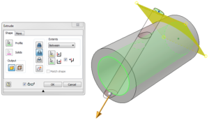
Solid Sweep was also improved to help users create more complex designs as well as improve performance when impacting multiple solid bodies.
Interoperability
You can now import and export .JT format with graphical PMI data. So the design intent captured with MBD/3DA can be passed when using .JT.
![]()
![]()
Assembly Modeling
Frame Generator and Tube & Pipe usability improvements continued to be enhanced with Inventor 2020.2. Content filtering, content placement, route definition, and in canvas interaction have all been improved.
![]()
With prior updates, we had added additional options when performing an Axis-Axis Constraint. And you let us know you liked the new options, but still wanted the ability to select legacy default behavior. We have now added the legacy behavior of Undirected as a default option.
Last year Tolerance Analysis inside of Inventor was added for Product Design and Manufacturing Collection subscribers. With the latest update, we have improved how constraints are recognized and added the ability for sub-assemblies to be supported in the stack-up detection. We have also added some in-product awareness as we found many of you were not aware you had access to the Tolerance Analysis toolset.
![]()
For a complete list of enhancements and fixes, please refer to the online Help and Release Notes.
Looking beyond Inventor 2020.2 – The Inventor Public Roadmap
![]() The Inventor team is excited to release our public roadmap. This past September marked 20 years of Inventor in the market. Many of you have been with us since day one. Many of you have been asking for a public roadmap for Inventor over the past couple of years. Our fellow Autodesk products have begun showing their public roadmaps for a bit now (Revit, 3ds Max, and Fusion 360), and we felt it was time we did the same with Inventor. We want to use the public roadmap as an extension of the Inventor Ideas page, Inventor Forum, and Inventor Feedback Community to show a high-level view of some of the projects in the queue. Many of you have provided feedback, tested alpha and beta builds, and engaged with the Inventor team throughout the years…and we love it. Hopefully, you find the public roadmap valuable and are excited to hear about what is coming in Inventor.
The Inventor team is excited to release our public roadmap. This past September marked 20 years of Inventor in the market. Many of you have been with us since day one. Many of you have been asking for a public roadmap for Inventor over the past couple of years. Our fellow Autodesk products have begun showing their public roadmaps for a bit now (Revit, 3ds Max, and Fusion 360), and we felt it was time we did the same with Inventor. We want to use the public roadmap as an extension of the Inventor Ideas page, Inventor Forum, and Inventor Feedback Community to show a high-level view of some of the projects in the queue. Many of you have provided feedback, tested alpha and beta builds, and engaged with the Inventor team throughout the years…and we love it. Hopefully, you find the public roadmap valuable and are excited to hear about what is coming in Inventor.
Before we get started, there are a few things our legal team wanted to remind you about:
This roadmap may make statements regarding future events and development efforts for our products and services. These statements reflect our current expectations based on what we know today. Our plans are not intended to be a promise or guarantee of future delivery of products, services, or features, and purchasing decisions should not be made based upon these statements. We do not assume any responsibility to update this roadmap to reflect events that occur or circumstances that exist after the publish date of this roadmap.
How do we decide what to develop for Inventor?
A good place to start is sharing how the product team delivers enhancements. We shifted how we deliver new functionality to our customers, starting with Inventor 2016. Rather than having you wait 12 months, we now look at how we can deliver enhancements as soon as possible throughout the year with product updates. The team has been hyper-focused on delivering on customer requests with each release. The result of this focus: since March 2016 the Inventor team has delivered over 275 customer-driven enhancements over the past 16 updates.
![]()
For a refresher on what is in each update, check out the Inventor What’s New from 2016 through 2020.2 here
The next thing we hope to share is how we choose the investment areas in Inventor. We try to have a balanced approach that provides value to existing users, introduces technology to meet industry requirements, and help us attract new users to Inventor.
The way we look at investment areas for Inventor is through the approach of:
![]()
We hope that gives you a bit of background. Now onto what we are working on next…
Goal of the Inventor Public Roadmap
The public roadmap is intended to be a snapshot of some of the projects we are working on. This public roadmap, by no means, is a comprehensive list of everything coming in Inventor. Our goal is to show you areas we are working on delivering, so you understand our direction and product focus.
Experience
Inventor 2020 delivered a refreshed UI that featured a “Light Theme.” The feedback we received was overwhelmingly positive. The one thing people did ask for: a “Dark Theme.”
![]()
Based on this feedback, the team has been working hard to deliver a Dark Blue Theme for Inventor that will give users who use both AutoCAD and Inventor a consistent look and feel.
![]()
Performance has been an area of focus for the Inventor team over the past few releases. The faster we make Inventor, the larger, more complex designs you create in Inventor. We consistently have users working on assemblies of over 400,000 components and have many users exceeding 1,000,000 component assemblies on a regular basis. Inventor will continue to have a focus on performance. Going forward, the team will focus on specific workflow bottlenecks our customers are seeing.
Recent Inventor releases and updates have also had a focus on Frame Generator and Tube & Pipe improvements. Based on your requests, we know we aren’t done enhancing these two design areas of Inventor and have targeted some key areas for improvement. Frame Generator notch types, geometry filters, in-canvas interaction, and file naming defaults are just a few of the targeted areas.
![]()
![]()
Tube & Pipe will also look to take advantage of the new file naming options as well modern panel framework to streamline your design workflows.
![]()
Many of these improvements are driven directly from your input and feedback on the Inventor Ideas page. We are looking to be open and transparent with you on what ideas we have considered, selected, and are working to implement. With each update, the team targets as many of your Inventor Ideas as possible in every area of the product. Look for upcoming improvements to Sketch Constraints, Browser feedback, MBD, Design Accelerators, Sheet Metal, and Drawings.
Automation
The Inventor team sees automation as more than programming and customizing Inventor. Our goal is really to give users the flexibility and capability to leverage iLogic and the API if they have a need to. But, at a higher level, Inventor should get better with each release in how it helps you streamline your workflows and automate many of the steps you take to complete a task. We will talk later on in this post on how we are working to identify these areas in the product. Let’s start with workflow automation examples.
A few releases ago, we introduced Design Views within Inventor parts (.ipt files). Design Views allows you to pre-define views of your part that can be used in MBD/3DA and 2D drawing workflows. For users that leverage drawing Sheet Formats, our goal is to automate as much of the 2D Drawing creation as possible. The first step is making it easier for you to select Sheet Formats and automate all of the initial view creations and BOM placement within your drawings.
![]()
Other workflow areas we are looking to deliver are around Unwrap and Sheet Metal designs. With Unwrap, we want to allow you to define multiple closed loops that can be set as rigid and will not deform as the part is unwrapped.
![]()
![]()
During a customer visit in Europe, they mentioned their Inventor Idea post and showed us their current Sheet Metal workflow they needed to perform to complete a design workflow. We’ve since seen similar needs in other accounts. The team is now building an option in the Sheet Metal Flange command to allow you to define a Flange angle by Face, Work Plane, or Surface. Taking steps and manual calculation out of the design process.
When we talk about Inventor automation, we must talk about iLogic. iLogic is the heart of Inventor’s automation engine, allowing users to configure, automate, and customize their designs. We want to make iLogic both easier to use and more powerful. Past Inventor updates focused on making iLogic easier to use with autofill, syntax colors, and geometry naming. Our next area of focus in adding additional functionality to allow the user to further automate their drawings with iLogic. iLogic will allow users to control position, colors, and line types of Dimensions, Annotations, Balloons, Views, and Sheets through iLogic rules and snippets.
![]()
Users with iLogic driven Inventor designs can also leverage this automation beyond the desktop with Inventor’s Design Automation APIs on Forge commercially released on October 28th.
![]()
One last area of automation is how you work with other Autodesk products alongside Inventor. We want to help you use native data, and consume design changes, as smoothly and easily as possible. AnyCAD support across different versions of Inventor (released in 2017.4) and for Fusion 360 (released in 2018.2). AnyCAD with Fusion 360 enables Inventor users to easily leverage their designs into Fusion 360 for advanced Simulation, Manufacturing, and Generative Design workflows without having to translate files. Likewise, Fusion 360 designs can be opened in Inventor. Both tools allow for associative updates when files are updated in their native design tool.
![]()
We have many of you working between Inventor and Revit, as well. Inventor and Revit interoperability is a large and complicated project and involves developers from both Inventor and Revit. Our first objective is to bring in Revit (.rvt) designs into Inventor in a way that is streamlined and associative to the native Revit file.
![]()
Insight
Insights is an early area of investment for us on the Inventor team. We leverage data and product analytics throughout the development process, for sure. But, Insight is different from that. Our goal is twofold. One: we want to make sure ware understanding how people are using Inventor, not just what commands they use. Two: can we show you these insights in a way that helps you use Inventor more effectively?
Our modernization project is a good example of this. Not only did we identify highly used commands to build first, but we also looked at how you used these commands in the context of your overall design process. (i.e. we know what the top 5 used commands are in Inventor. But, what we really want to know is how they are used in a design workflow). We call this command flow.
![]()
As we have moved commands to the modern panel architecture, we have been able to streamline many of these command flows and improve usability. We have been able to validate and measure this improvement by comparing old and new command flows and have also verified with good old user testing. Test results showed over a 30% drop in click counts, and far faster finish times thanks to things like sketch integration and presets. Here are the eye-tracking results of an experienced user testing the Hole command that was moved to the modern panel architecture in Inventor 2019.
![]()
The Hole command is now easier and faster for you to use. This is the idea behind the new command architecture. And, you will see it more and more going forward in Inventor.
Summary
Ultimately, we want all our Inventor enhancements going forward to be driven by all three of these focus areas. By being focused on Experience, Automation, and Insight, we are staying focused on you: The Inventor User.
Get involved
As mentioned above, we love hearing from Inventor users. The Inventor team talks to customers every day via the Inventor Ideas page, and the Inventor Forum. As part of the Inventor Feedback Community you can get much more information on the projects we are working on for Inventor, and get to test out alpha and beta builds through your browser. We encourage you to be involved in any or all these communities and make your voice heard!
On behalf of the entire Inventor team, I truly thank you for being an Inventor user. We look forward to hearing from you!
Regards,
Loren
@lorenwelch
![]()
Loren Welch is a Sr Product Manager for the Inventor product line at Autodesk. Loren has over 20 years of industry experience in multiple CAD/CAM/CAE/PDM software applications and rapid prototyping solutions. He has been at Autodesk since 2008, where he currently manages release planning, product roadmap, and customer engagement for the Autodesk Inventor product line.
The post Inventor 2020.2 Update and Public Roadmap appeared first on Inventor Official Blog.


 Kevin Robinson


 Jim Byrne joined Autodesk in 2013 on the design and manufacturing marketing team. Prior to joining Autodesk, Jim worked at a local reseller for 14 years selling and supporting CAD, Simulation, and data management solutions. He also has three years of experience in the industry as a machine designer.


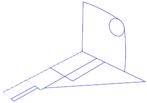
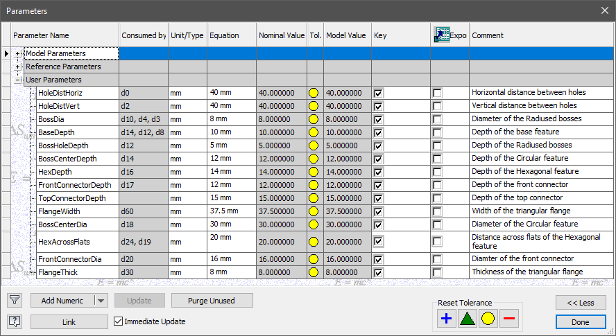
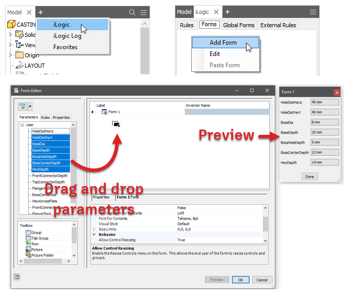
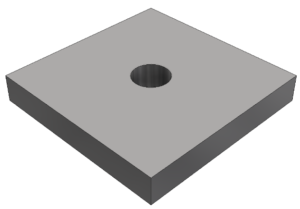 If I gave you a model of a 50mm by 50mm by 6mm steel plate, with an M10 clearance hole through the middle of the face, and asked you to change the width of that plate – what should happen to the hole?


 . While annoyed at first, my attitude quickly changed, as I began hearing about a new technology referred to as Rubicon aka Inventor R1. As the junior application engineer, I wasn’t yet in the need to know camp, but I heard enough to get super excited about the potential to learn another new CAD tool…… Fast forward 20 years and I am lucky to be part of the Autodesk Inventor team, then, more importantly, hundreds of customers and thousands of users I have engaged with since that first moment I learned of Inventor. Next week
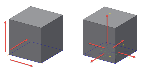
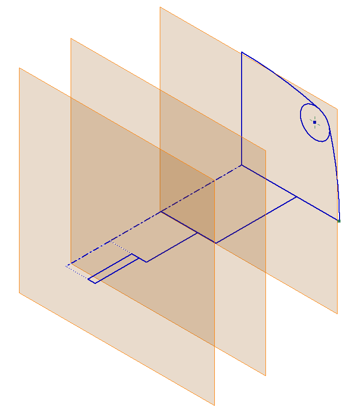
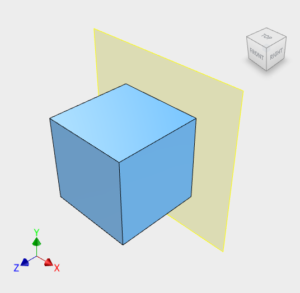 Traditionally Engineers have always drawn components from the front. This makes the coordinate system:
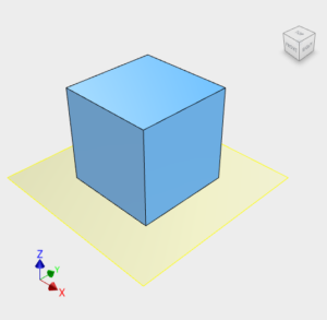 Traditionally Architects have always drawn their building layouts from the top. This makes the coordinate system:
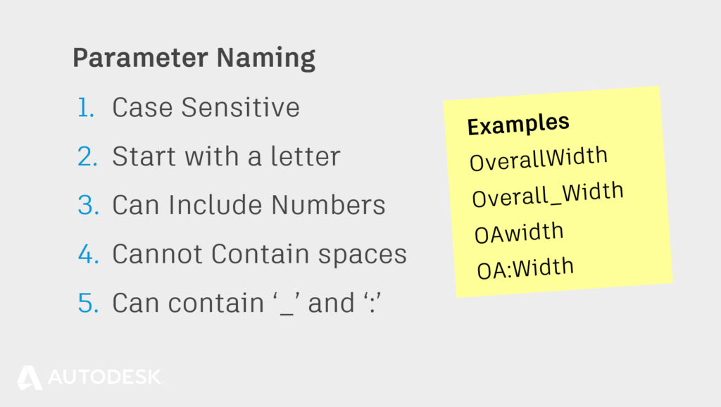
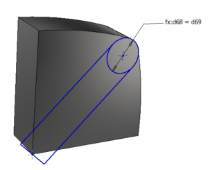
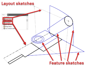
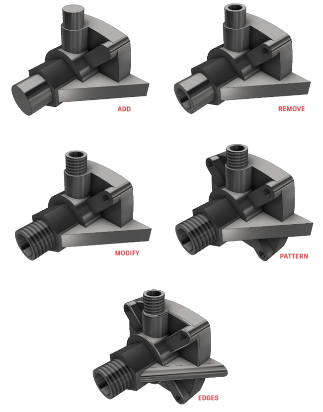
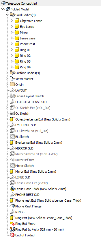
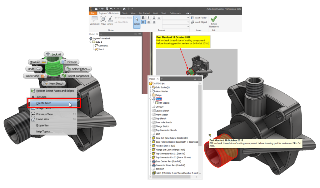
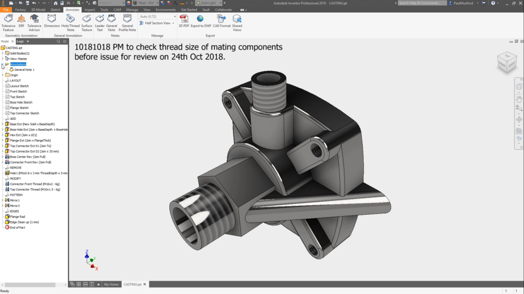
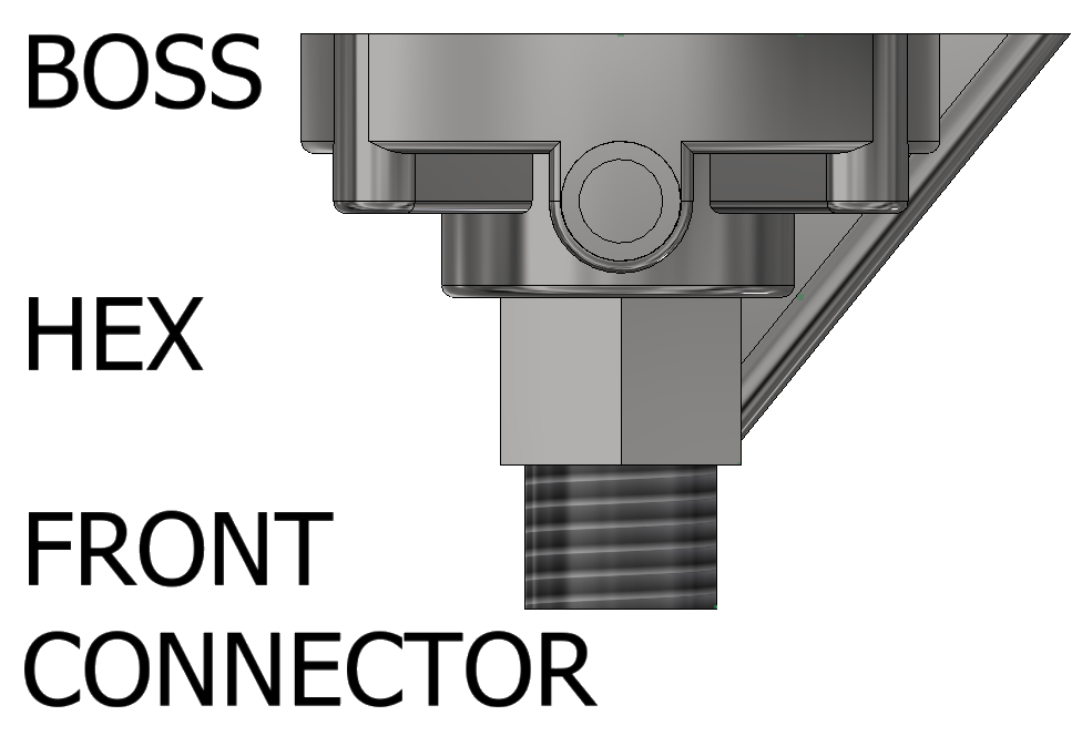
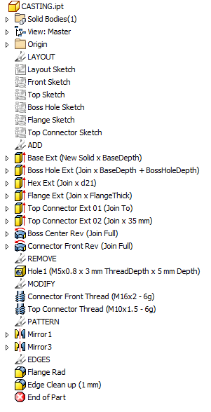 Feature Naming


 Lars Christensen is an award-winning Design & Manufacturing Expert who helps people that haaa-ate struggling with their CAD&CAM Software.


 Marc joined Autodesk in 2014 as a Design & Manufacturing Technical Specialist. Recently he joined the Product Marketing team. He is responsible for product marketing for the design and manufacturing software that makes up the Product Design and Manufacturing Collection but, more specifically, the collaborative tools (i.e., Vault and Fusion Lifecycle).


 The Inventor team is excited to release our public roadmap. This past September marked 20 years of Inventor in the market. Many of you have been with us since day one. Many of you have been asking for a public roadmap for Inventor over the past couple of years. Our fellow Autodesk products have begun showing their public roadmaps for a bit now (


