The Autodesk Design and Make conference is our chance to celebrate the awesome work that you do.
Each year, thousands of people gather at Autodesk University, and hundreds of speakers share their stories, best practices, and top tips for success with technology for design and engineering.
I first started to present at Autodesk University in the year of 2010. This was the year when my 1st book, Up and Running with Autodesk Inventor Professional, was released worldwide.
So I was excited and nervous at the same time to present content from my book for my first class at Autodesk University.
I have never looked back and have been presenting at Autodesk University to this date, despite the long and tiring travels to USA.
The reason I keep doing this is that I frequently get comments like ‘your book has been a life saver for me’ and ‘ Mr Younis your book has greatly helped me in my job’.
Another reason for attending it give me the opportunity to share my new content with designers and engineers around the world and to get feedback in helping me to make better content for my next book project.
Finally, I would like to say Autodesk University is a great platform to network with like-minded professionals from around the globe, and now looking forward to AU2024.
‘Up and Running with Inventor Nastran’by Wasim Younis
Check out the class.
All AU class materials are accessible for free on the Autodesk University website and can include video recordings, presentations, handouts, and datasets (depending on the class type).
This year marks a monumental milestone for 25 years of Autodesk Inventor, a quarter of a century of designing and making your best products. This release brings over 142 enhancements, each carefully crafted to improve user experience, enhance functionality, and streamline design processes. We’ve also tackled over 1330 bug fixes, demonstrating our commitment to reliability and performance.
Check out the following video demonstrations for enhancements to part and assembly modeling, sheet metal, drawings, and interoperability. If you want to learn more and ask questions to the experts, then be sure to register for the upcoming webinars listed at the end of the article.
Part Modeling
Inventor 2025 continues to build on the momentum of the 2024 updates by introducing several significant enhancements to part modeling capabilities, particularly in the Finish Feature functionality. Watch the following video to discover improvements for faster, more efficient workflows.
Sheet Metal
Inventor 2025 introduces a modernized interface for designing sheet metal components, making the process more intuitive and efficient than ever before. This latest release boasts a sleek, user-friendly UI that streamlines the design workflow by placing tools in a logical order and making previously hard-to-find features readily accessible.
Assembly Modeling
Let’s look at the improvements to assembly modeling, including some much-needed graphical updates like highlighting the hidden sections of components.Quickly change the color of all parts in your assemblies using customizable color schemes. Discover a new option for “Oriented Minimum Bounding Cylinder” when using cylindrical envelopes to simplify your assemblies. And speed up fastener placement when creating assembly-level patterns.
Drawings
There’s a plethora of “Just-Do-It” enhancements to optimize drawings, documentation, and annotations. Starting with a heavy hitter is the ability to insert “item number” to drawing leader text. This new functionality enables dynamic updates to text that are linked to the parts list, as well as to balloons and notes within drawings, ensuring that documentation remains consistent and accurate throughout the design process.
Interoperability
Next, we’ll explore the advancements for interoperability within the Autodesk ecosystem, focusing on enhanced compatibility and seamless integration with AEC applications to facilitate smoother and more efficient workflows.
Conclusion
In this release of Inventor, we have emphasized our commitment to making it the premier tool for engineering and design. It brings a series of features and functionalities that streamline your design process, improve your user experience, and promote interoperability, ensuring that you’re equipped with the most advanced tools that work exactly how you expect them to.
Register to learn more
Be sure to register for our upcoming webinar series to learn more about Inventor 2025 and ask questions to our experts.
The Inventor team works hard to develop the tools that promote efficiency in your design and manufacturing workflows. Many of the tools we implement in Inventor begin with the great ideas we receive from designers and engineers who use our software. Your complete success is a combination of the software that helps your ideas take shape and the connection you have with Autodesk, Autodesk partners, and other companies that use Inventor. Review the resources below to find ways to connect!
Access Inventor pre-release versions for the latest concepts, features, technology, and discussions with the Inventor team; provide candid feedback about your needs to help improve Inventor.
Created by the community for the community, Autodesk App Store for Autodesk Inventor helps you achieve greater speed, accuracy, and automation from concept to manufacturing.
The State of Design & Make report is a global annual study for leaders who design and make places, objects, and experiences. It identifies the most pressing issues shaping today’s businesses and helps leaders make informed, strategic decisions about how to prioritize and invest in the future.
For three decades, AU has been at the heart of Design and Make industries. It brings together innovators in architecture, engineering, construction, product design, manufacturing, media and entertainment, to share ideas, advance industry practices, and explore opportunities for the future.
Learn from the experts regarding topics for design and manufacturing. Register for future webinars to watch them live and watch recorded sessions on-demand.
A middle school robotics team in Michigan is discovering the power of 3D modeling with help from Autodesk Inventor software. Led by a parent with no previous engineering experience, the team uses the software to visualize concepts, build 3D models, test prototypes virtually, and 3D print parts. This middle school team is bringing their ideas to life, learning CAD, and getting inspired to pursue careers in engineering. The end result is a fully functional robot that is ready for competition happening across the globe.
Starting from zero
Matt Bombich had served as a police officer, worked in the crime lab, joined the bomb squad, and was even a morgue photographer. So when his middle-school-aged son asked him to lead the after-school robotics program, he was mostly confused.
Vicksburg Control Freaks team leader Matt Bombich and his son
“I told him I didn’t know a single thing about robotics,” Bombich says. “But I jumped in anyway. And it’s been pretty great. In fact, it’s completely changed my career path.”
More on that in a bit.
For now, let’s focus on the program Bombich has been leading for more than a decade. It comes from For Inspiration of Science and Technology (FIRST), a global nonprofit that sponsors team-based robotics programs to advance education in STEM and prepare young people for the future.
FIRST is a global nonprofit organization that prepares young people for the future.
At Vicksburg Middle School in Vicksburg, Michigan, Bombich leads Control Freaks, a FIRST Tech Challenge team. During this year-long competition, students must design and build an 18-inch robot that can complete a series of tasks, both autonomously and under the control of an operator.
The competition kicks off with a “challenge video” that explains all of the tasks the robot needs to achieve in order for the team to score points. The robot competes on a 12-foot by 12-foot field, where it needs to visit specific locations or pick up objects from one area and set them down in another. If this sounds like a quiet, science-fair type of experience, think again.
FIRST Robotics state competition in Howell, Michigan
“It’s very intense,” Bombich says. “People are in the stands cheering. Music is blasting. It’s a great atmosphere. We try to compete hard without trashing the competition. It’s very collaborative.”
The team attends two district competitions each season. Performing well at these events means a trip to the state competition and, from there, to “worlds,” where middle and high school teams from around the globe compete against one another.
Vicksburg Control Freaks 2023 state qualifying team
Winning these competitions can be very satisfying, of course. But the most meaningful impact of the program is on the lives of the students. With Bombich as their guide, they work together after school to solve real-world design and engineering problems. It’s a process that pays big dividends.
Vicksburg Control Freaks 2024 high school team prepares for competition
“I’ve had five students now who have chosen a career path in engineering as a direct result of this program,” Bombich says. “One recent graduate spent a year with a mentor learning Java programming. Now, he’s studying computer engineering at Purdue. Before he joined the robotics program, he didn’t really have any sense of what he wanted to do with his life. Programs like this make a huge difference.”
Bringing ideas to life in 3D
If Bombich started out totally unfamiliar with robotics, he was even less familiar with the design program his son (now a college junior by the way) was using in school. It was called Autodesk Inventor, and at first glance, it looked pretty complicated.
“I started out using Sketchup to help the kids design various parts of the robot,” Bombich says. “Then my son suggested we use Inventor since he was already familiar with it. It looked very complex at first. But then I watched him use it. We would create a design and tweak it together.”
Then Bombich introduced Inventor to the robotics team. As you can imagine, it was a difficult step for middle schoolers to take. But by the second year of implementation, the team could create the entire design of the robot in CAD, working together in Inventor. From Bombich’s perspective, the biggest benefit of Inventor is its ability to help students visualize their ideas.
“Recently, I had two students describe an idea to me in words, and it just wasn’t making sense,” he says. “So we sat down with Inventor, and I had them tell me what to draw. Fifteen minutes later, we had their mechanism built out, and they could see right away that it wasn’t going to work the way they thought it would. So they started making changes. Eventually, we incorporated their idea into the final design of the robot.”
Vicksburg Control Freaks 2023 middle school robot
With Inventor, the robotics team goes through many of the same steps as any other manufacturer. They start with an idea and create a CAD model of each part. Then, they build a prototype and test it virtually. With each iteration, the group weighs in with feedback until the production-ready design is finished and the final robot can be produced and assembled.
“Inventor has completely revolutionized our program,” Bombich says. “We save time. We save materials. If there is a problem with a component, we can create a new version very quickly. At one competition, we had a support component for a pulley that kept breaking. So, on the fly, we added some gussets and ribs to the design and changed the density of the plastic in the slicer program. We had a new part 3D printed in about 90 minutes.”
In another memorable instance, the team worked through 13 iterations of the robotic “claw” hand that needed to pick up two plastic pucks and then drop them one at a time.
Design iterations of the robotic “claw”
“It took a lot of tries to get to the final design,” Bombich says. “We changed the width and the number of fingerlets. We added a gap to accommodate the hexagonal shape of the puck. We reduced the material on one ‘finger’ of the claw to adjust its tension so it could drop one puck but not the other. In the final version, we added a way to grab the puck by wrapping around it, which worked very well.”
Putting the “team” in teamwork
The team takes their 3D printer to every competition in anticipation of these kinds of issues. In the spirit of collaboration, they also put it on display so other teams can stop by and take a look.
“Many teams do not have access to a 3D printer,” Bombich says. “So we put our 3D model up on a monitor and print a part so they can see exactly how it works.”
It was a similar interaction that led Bombich and his students to start using Inventor CAM.
“We were talking to a high school team about how to make polycarbonate parts, because their robot had worked really well, and we noticed that their material was much more resilient,” Bombich says. “I asked them how they made their parts, and they recommended a specific CNC mill. Up to that point, we had been sending out for laser cutting of aluminum. As it turns out, the CAM capabilities for Inventor were very easy to download and the learning curve wasn’t that steep.”
CNC mill driven by Inventor CAM
Within a couple days of having the CNC mill in-house, the team was cutting parts.
“It takes about 10 to 15 minutes to put a piece of plastic on the CNC mill and turn the cut file into a part that is ready for assembly,” Bombich says. “That’s hard to beat!”
Changing models… and career paths
Bombich and the robotics team are still learning about Inventor and how to get the most out of it. Part of this comes from working with others who know the software and can share new keyboard shortcuts, for example. But it also comes from experience.
“I like the parametric constraints, and I’ve learned how to use them a little bit better by watching videos and reading the Autodesk forums,” Bombich says. “There is a design accelerator for pulleys that has been helpful. We can produce a new one in a few minutes with the same profile but a different tooth count. Using the template, Inventor does a lot of the work automatically.”
What Bombich likes most, however, is how Inventor helps the students learn CAD themselves.
“It’s incredible to watch,” he says. “We have two high school kids who help us out and provide mentoring. And this year they helped a couple of our students start learning CAD. It was amazing. They started to understand what types of problems can be solved with 3D modeling. They learned how to manipulate the model. They learned the terminology and how to ask the right questions.”
This knowledge transfer aligns very well with the larger goal of robotics programs like these.
“Big picture, it’s about building a competent workforce that can create the models and run the machines,” Bombich says. “Manufacturing companies are looking for workers with mechanical aptitude who can contribute to every part of the process.”
Nobody knows this better than Bombich, who is pursuing a career change based on his experience with the robotics team.
“There was nothing like this program when I was in school,” he says. “I guarantee I would’ve become an engineer if there had been. But it’s never too late! I recently decided to leave forensics and find work in engineering. And I just landed my first job.”
Seven tips to guarantee that Your Autodesk Inventor Sheet Metal models will flat pattern without errors.
‘Failure in creating a flat pattern.’ Who needs it? No one wants to create an Autodesk Inventor sheet metal part that won’t unfold!
The Inventor sheet metal environment is designed to flat pattern ‘developable’ geometry. Think of the shapes you can make from a flat sheet of metal and a brake press.
Inventor will not flat pattern ‘pressed’ shapes—for example, a car door.
Inventor has a dedicated modeling environment for creating sheet metal parts, and Inventor will also develop flat patterns for imported components from other CAD systems.
In this blog post, I’ll give you my top seven tips for ensuring that your sheet metal parts will flat pattern every time.
#1 Model with Autodesk Inventor’s sheet metal environment
OK. This tip is kind of obvious. Creating a 3D model in the Inventor Sheet Metal environment that won’t develop is rare.
Using derived workflows (skeletal modeling) to create Sheet Metal assemblies can cause issues if you don’t pay attention.
Creating multi-body models directly in the sheet metal environment is a cleaner workflow because you have all the sheet metal tools and styles available.
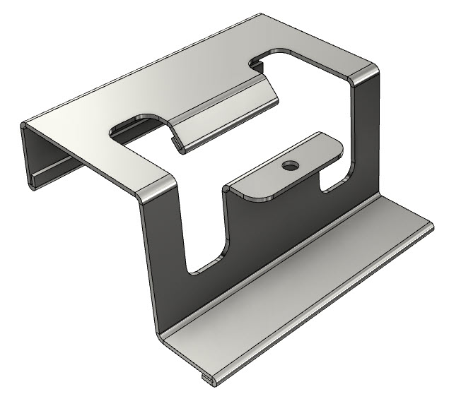
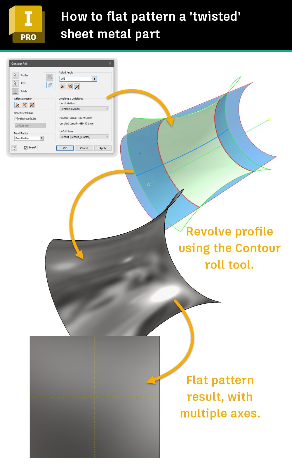
Some imported geometry contains forms that won’t develop. However, you may be able to model them Inventor’s sheet metal environment. Check out this image of a ‘twisted’ component built with Inventor’s sheet metal contour roll tool.
How to flat pattern a ‘Twisted’ Sheet Metal Component.
Use the Sheet metal tools to model your Sheet Metal parts if you can. If you can’t, check out the tips below.
#2 Leave a gap
Your model cannot be completely continuous. Make sure you leave a gap to allow unfolding.
Inventor’s ‘Rip’ tool can add a gap to parts that don’t have one.
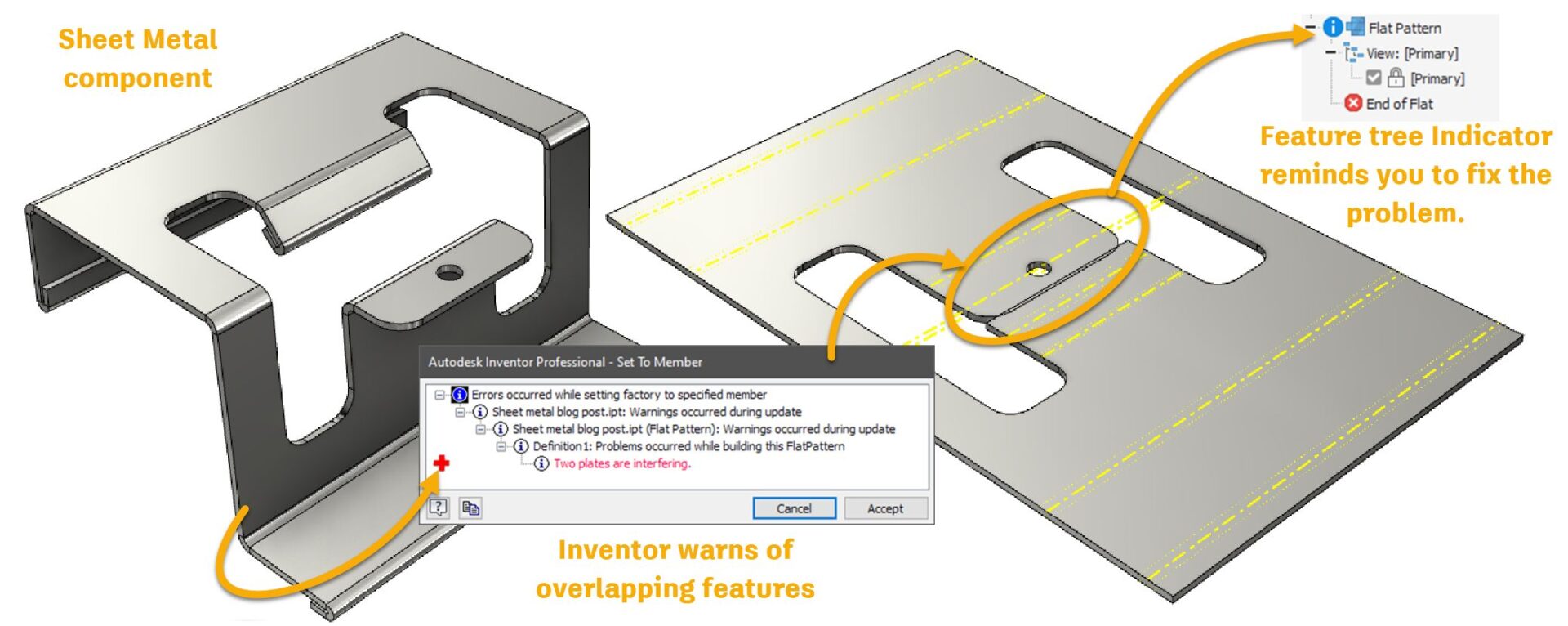
#3 No overlapping folds
The Autodesk Inventor Sheet Metal environment has a great tool for detecting overlapping folds.
Although you can develop a flat pattern with overlapping folds, Inventor will complain about it and won’t stop complaining until you fix it!
If you are using the Sheet Metal environment, you can adjust your flanges to prevent to prevent the overlap.
If you are working with imported files, you could use Autodesk Inventors direct modeling tools to fix the problem features.
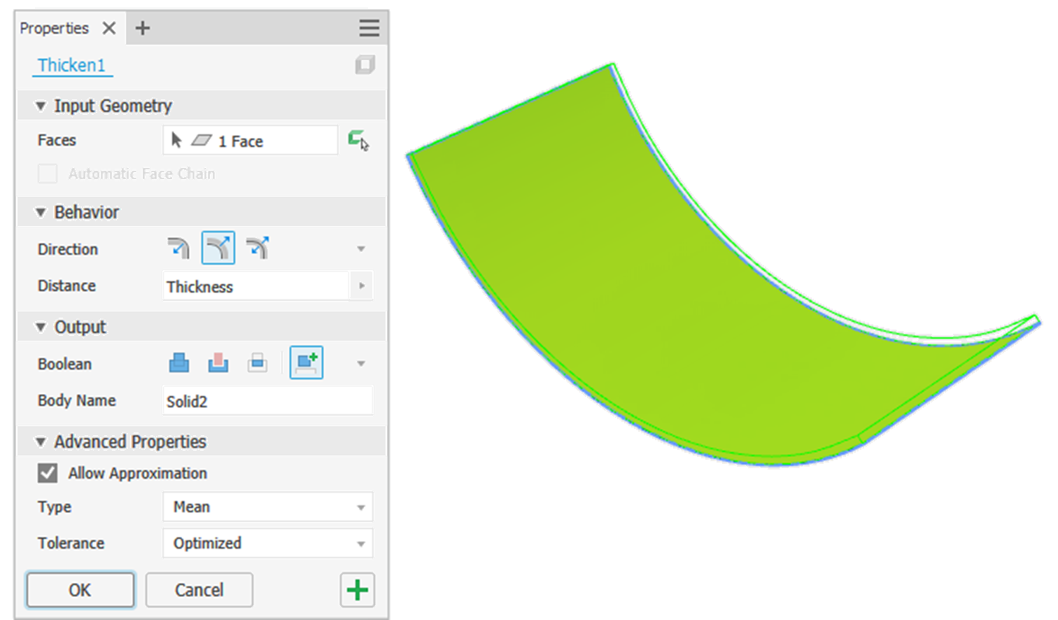
#4 Consistent Thickness
To develop a flat pattern, Autodesk Inventor must start with a model that has a consistent thickness—just like a sheet of metal in real life.
This issue often arises when you build a ‘master’ component, split it up, and derive the bodies into Sheet Metal parts.
My top tip for this workflow is to model using surfaces and then use the thicken command in the part modeling environment to model a solid with a constant thickness.
You can thicken the surface in the Multibody part and derive the body into a sheet metal part, or derive the surface into a Sheet Metal part and then Thicken in the Sheet Metal part file.
Note: The thickness of your model must be the same as the value of the sheet metal Thickness parameter of the current sheet metal style you are using.
When importing models to the Sheet Metal environment, Inventor will try to guess the thickness of an imported component. To set this manually, measure your part’s thickness and then override the Sheet Metal ‘Thickness’ parameter in the Active Sheet Metal Style to match the thickness of your imported model.
#5 Perpendicular edges
Inventor doesn’t like developing flat patterns of parts that have wobbly edges!
Use the Thicken tool to build your model from surfaces to ensure that your model’s edges are perpendicular to the face.
When building Sheet metal components, make sure your cuts are perpendicular to your faces using the options available in the cut tool’s dialog box.
One tip to ensure cuts have perpendicular edges is to use the split face tool and then the Thicken tool—referencing the sheet metal ‘Thickness’ Parameter to remove the unrequired section (See image).
#6 External fillets
Inventor won’t develop parts that have folds with 90-degree external edges.
Inventor will develop flat patterns from components with folds with 0-degree internal edges, but the external edge of the fold must have a radius.
Zero-degree internal corners were added for customers using Inventor’s Sheet Metal tools to develop designs from material such as cardboard that ‘crush’ a lot more on the internal edges than Steel does.
#7 Developable Surfaces
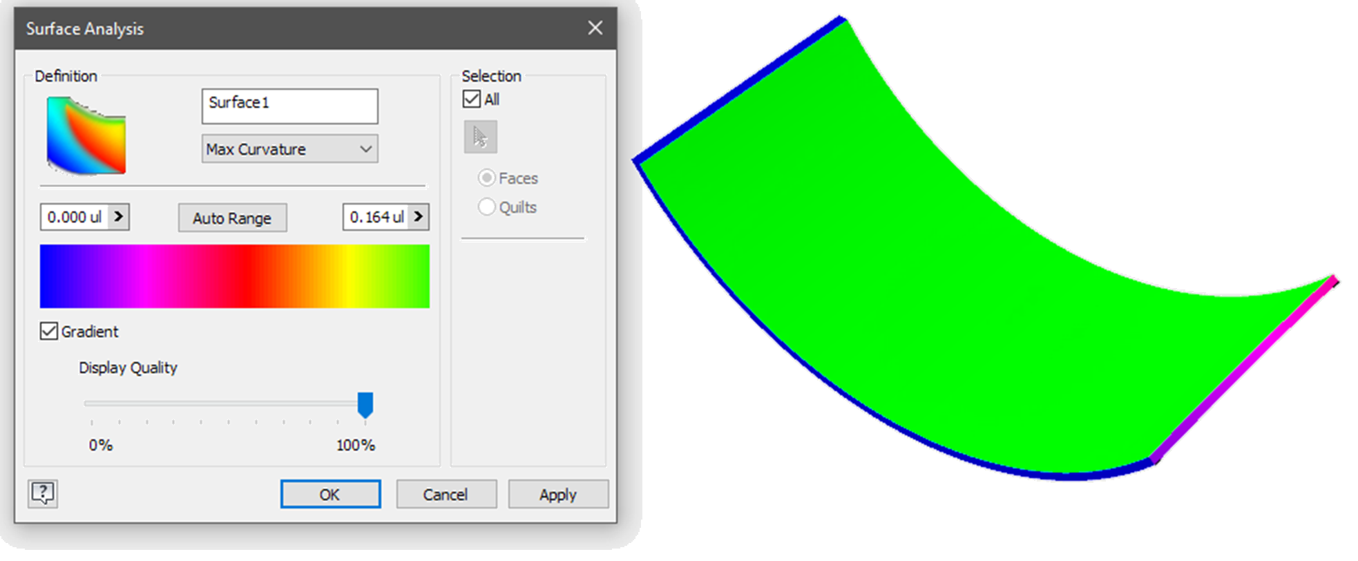
To flat pattern a Sheet Metal component, your design must be ‘Developable’.
A developable surface is a single curved surface that can be flattened without distortion.
A developable surface will always be a ‘ruled surface’. A ruled surface is a surface on which you could hold a rule at any point, and by twisting the rule, find a direction where the rule would touch the surface, all along its straight edge.
However – a Ruled surface is not always a Developable surface, such as in the case of a double-ruled Hyperboloid.
Developable surfaces include planes, cylinders, and cones. Non-developable surfaces, such as spheres and nurbs surfaces, have compound curves.
If Inventor has trouble flat patterning a part, select a face on the part before you use the flat pattern tool. The ‘A’ side tool is equivalent to making this section permanent.
Use the sheet metal bend tool to add bends to square corners. Right-click on a bend and edit it to turn it into a corner.
If you have imported a component from another software package and you are really struggling to get a flat pattern, use Inventor’s curvature inspection tools to look for areas that are not flat, faces that are not parallel (Equal thickness), or edges that are not perpendicular to the faces.
Before you start modeling parts for sheet metal fabrication, talk to the fabricator to see what they can achieve for the budget you want to spend!
Here are some basic rules of thumb for sheet metal design.
Speak to your fabricator before starting your design.
Ensure that the thickness you define is available in the material you want!
Allow bend relief.
Inside bend radius equal to the material thickness (Minimum). This may need to be increased with materials like aluminum that are subject to cracking. Manufacturers typically have dies in limited sizes – so check first.
Minimum hole diameter is equal to material thickness.
Keep holes at least one material thickness from the edges of the part.
Keep holes at least 3 x Material thickness away from bends to prevent the holes from becoming distorted.
Avoid short flanges (four times material thickness)
Maximum boss depth = three times thickness.
The length of at least one ‘U’ channel leg must be equal to or less than the internal dimension across the base of the ‘U’.
‘Find elegant solutions to your most interesting problems.’
Looking for insight, guidance, and tips on how to use the latest tools and technologies to design and engineer better products? You’ll find classes, articles, short talks, and more to help you work smarter, design better, and engineer better products with the new Design and Engineering page on the AU year-round learning site.
AU (Autodesk University) is Autodesk’s flagship customer event, but the learning doesn’t stop when the in-person event is over. On AU Online, you can find on-demand class videos, handouts, and data sets, so you can enjoy learning from industry experts, partners, and your peers the whole year round—it’s all free, no log-in required.
How will I find learning content for design and engineering on AU-online?
To help you find the product design and engineering content you need, we’ve created a landing page that curates design and engineering content from AU specifically for you.
AU online for Product Design & Engineering. Find elegant solutions to your most interesting problems.
General Session: Hear Autodesk’s long-term view for our key industries and how we will support our customers.
Industry Forums: Dive into Autodesk’s near-term view, specifically on the design and manufacturing (D&M) industry.
Theatre talks: Get big ideas in short talks from thought leaders—from pioneering projects to industry-changing innovations.
Featured articles: Read up on important new technologies, product design and engineering trends, from agile product development to better product performance.
Trending classes: Explore the classes that are most viewed by your peers.
Playlists
Check out curated lists of classes on product design and engineering topics, including;
A large number of occurrences can promote a warning to use Optimized compute.
Autodesk Inventor Optimized compute
When creating patterns in Autodesk Inventor, Inventor checks every new instance of your pattern to see if it must create new faces.
In the image below, we can see that Inventor will need to calculate new faces where the patterned feature integrates with the body of the part, and it won’t need to create new faces where the patterned feature interacts with a cutout.
Calculating a feature pattern across a body with voids.
Turning on ‘Optimized compute’ tells Inventor that there are no additional features that the pattern needs to interact with, so it can get on and build the pattern.
To turn on Optimized compute, expand the part feature pattern dialogue by clicking on the ‘>>’ arrow button and select the radial button next to ‘Optimized.’
Using the ‘Optimized’ option for patterns in Autodesk Inventor.
Warning!
This option will fail if you are patterning over the top of an existing feature. It will work out OK if you create any additional cuts after your pattern.
TIP: If you see an error, In the warning dialog, expand the nodes until you see a node with red text and a red cross beside it. Click on the red text and the problem feature will highlight.
Tip: Click on the red text in the warning dialog for a visual clue on where the feature is failing to compute. In this case, it’s where the feature pattern hits a void.
An alternative method
You may get a better result if you create a cut feature as a body, and then pattern the body instead of patterning the cut.
An alternative is to model the feature, and then pattern it as a feature or body.
Using this method, Inventor only has to copy the body rather than analyzing the interactions between faces.
Examples
Workflow
Part file size on disk
Pattern generation time
Cut first then pattern
700 KB
415ms
Pattern with optimized compute then cut
750 KB
150ms
Pattern body then cut
800 KB
1430ms
Your results may vary depending on the version of Inventor you are running and your hardware specs.
Conclusion
If you are having trouble with large feature patterns In Inventor taking a long time to compute, giving you large, unwieldy file sizes, or even crashing Inventor entirely, consider changing the order of your features and patterns and try the ‘Optimized compute’ option!
Five Autodesk Inventor iLogic productivity hacks for non-programmers
‘Yeah—that can probably be done with iLogic.’
Did you ever hear this and wonder—HOW?
iLogic in Autodesk Inventor is a rule engine that utilizes the intelligence already built into your design to create a configurable model or automate your processes.
iLogic is designed for individuals unfamiliar with computer programming, but getting started can still be daunting.
In this series of posts, I will give you five iLogic productivity hacks—easy examples that will help you get started with iLogic.
Why you should add an input form, using Inventor iLogic.
Have you ever opened a part file for editing and thought, “Errrguh! Where do I even start?”
It may have been modeled by a colleague. It might be a part YOU modeled months ago, and you’ve forgotten what you were thinking (we’ve all been there).
No wonder we resort to direct editing or give up and remodel parts from scratch.
Building a part with clear design intent can save us hours fighting with—or even rebuilding—a model. But communicating design intent can be even more important. How can we leave instructions in a part file to say:
“How have I designed this model to change? Let me show you!”
By adding an iLogic form to a parametric part model, we can easily communicate design intent. We can make it clear exactly which parameters should be changed and by how much, and indicate what the effect on the design will be.
In the iLogic browser, LMB click on the ‘Forms’ tab.
RMB click anywhere in the iLogic browser, and choose ‘Add Form’.
The iLogic form editor will open, along with a preview of the new form.
To add controls to the form, drag and drop from the Parameters section on the left, to the form building area on the right. You’ll see the form preview update as you work.
You can change the form control type from a simple input box to other types such as a radio control or slider, or limit the inputs to help control the design intent.
The Autodesk Inventor iLogic form builder
You can even add an image to the form to better communicate how your model is designed to change and anticipate how the controls on the form will change the model.
Tip: iLogic forms and rules are typically saved in the file you are working in, meaning the changes you’ve made aren’t saved until you save the open file. When working on your own iLogic projects, save your files regularly to save the changes to your iLogic Rules and Forms—or explore external Rules.
That was fun! What can I learn about iLogic next?
Coming soon, how to use Autodesk Inventor iLogic to make sure that data is added consistently.
How can I find out more about Inventor iLogic?
AU (Autodesk University) is Autodesk’s flagship customer event, but the learning doesn’t stop when the in-person event is over. On AU Online, you can find on-demand class videos, handouts, and data sets, so you can enjoy learning from industry experts, partners, and your peers the whole year round—it’s all free, no log-in required.
To help you find the product design and engineering content you need, we’ve created a landing page that curates design and engineering content from AU specifically for you.
In this exercise, we’ll see how iLogic can help us with a different type of conformance–this time, conformance with our data standards.
3D parametric design software has many advantages over technology such as 2D CAD or hand drafting. Most of these advantages benefit the designer. However, there is one advantage of modern CAD that benefits everyone involved with your project—Data.
The ability to provide the data from your design in a format that your colleagues can use helps to reduce data re-entry, meetings, and mistakes–increasing the quality of your process and reducing overall time on your project.
The trick is ensuring the data is entered consistently and correctly from the start…
You don’t have to fill out every iProperty that Inventor offers, but you do need to fill out the required iProperties every time.
So, let’s learn how iLogic can help us with data conformance.
Autodesk Inventor iLogic form for Data Compliance.
I hope you can see how this iLogic form will help users understand which iProperties they need to fill out for this Part document.
Let’s not rely on the user to remember to trigger this form. Let’s create an iLogic Rule to remind them (iLogic code is called a ‘Rule’).
Here is the logic for this Rule, written in longhand:
When this file is saved, If the iProperties ‘Author’ or ‘Part Number’ or ‘Description’ or ‘Eng. Approved by’ or ‘Eng. Approved date’ are empty – then open the form DATA CHECK.
Autodesk Inventor creating an iLogic Rule for data conformance.
In the iLogic panel, LMB click on the Rules Tab.
In the iLogic panel, hover your cursor over an empty space, and RMB click.
Choose Add Rule from the flyout.
The ‘Rule name’ dialog will open. Type DATA CONFORMANCE RULE into the input box, and LMB click the OK button to create your rule.
The iLogic Rule editor will open.
In this tutorial, I aim to get you started with iLogic as quickly as possible–so I won’t explain the iLogic editor in depth.
Copy and paste the following code from this blog post into the iLogic code editor:
If the iProperty ‘Description’ string is not empty (it has any value), do nothing.
If the iProperty ‘Description’, contains an empty string, then open the form ‘DATA CHECK’.
It examines the remaining iProperties in the same way using an ‘Or’ statement. If this is true, OR this is true, OR this is true, OR this is true—then, do this….
We are done coding for now. From the iLogic Rule editor dialog, in the bottom right-hand corner, LMB click on the Save button. From the same place, LMB click on the Close button.
Nothing happened? OK! That’s expected.
Set an iLogic rule to run before the document is saved.
The action of Saving a file is known as an ‘Event’. An Event can start something happening. This Event is now known as a ‘Trigger’.
When the user saves this file (the Event), we want to Trigger the iLogic rule we called ‘Data Conformance Rule’.
Let’s learn how.
Launching the iLogic event triggers
Navigate to the Manage Tab > iLogic Panel.
LMB click on the Event Triggers button.
On the right-hand side is a list of Events. Note the Event Before Save Document.
On the left-hand side is a list of iLogic rules in this document. Note our iLogic Rule Data Conformance Rule.
From the Event Triggers dialog, Rules in this document area, LMB click-and-drag the Data conformance rule into the Rules On Events area, and drop it (let go of the LMB) under the Before Save Document Event.
Set your Autodesk Inventor iLogic rule to run using an Event trigger.
You have now attached your iLogic rule to the Before save event, meaning that your rule will run before this document saves.
Let’s test!
Try saving this Part document. The action of saving this file will run the ‘Data compliance rule,’ which will check to see if the iProperties are empty, and if they are – the ‘DATA CHECK’ form will open so that our user can easily fill out the required information.
Tip: iLogic forms and rules are typically saved in the file you are working in, meaning the changes you’ve made aren’t saved until you save the open file. When working on your own iLogic projects, save your files regularly to save the changes to your iLogic Rules and Forms—or explore external Rules.
That was fun! What can I learn about iLogic next?
Coming soon, how to use Autodesk Inventor iLogic for ‘Top down’ design.
How can I find out more about Inventor iLogic?
AU (Autodesk University) is Autodesk’s flagship customer event, but the learning doesn’t stop when the in-person event is over. On AU Online, you can find on-demand class videos, handouts, and data sets, so you can enjoy learning from industry experts, partners, and your peers the whole year round—it’s all free, no log-in required.
To help you find the product design and engineering content you need, we’ve created a landing page that curates design and engineering content from AU specifically for you.
Inventor 2025.1 will be released today! This update is packed with enhancements for part modeling and assembly modeling, sheet metal, drawings, and interoperability.
Sketch environment
You can now copy and paste multiple sketch blocks within the same document or from one file to another. This also works between folded and flat parts in the same document.
Quickly turn on and off snap options for Endpoint, Midpoint, and Center for more control as you apply new sketch entities.
Part enhancements
Thread data is now available for both parts and assemblies when using the Measure command. This applies to any face that has associated thread data.
Thread Designation
Thread Class
Thread Depth
Thread Direction
When creating a new Model State, iPart, or iAssembly, you now have the option to rename them immediately.
Presets have been added to the Thicken / Offset feature providing quicker data entry for common behavior, output, and advanced properties.
Access to the XLS file for the Hole, Thread, and Finish features is easier and consistent for making modifications to the data.
Assembly enhancements
The option to “Lock Rotation” for the Insert constraint is now available in the context menu to quickly switch the setting.
The Bolted Connection dialog now displays the number of selected reference points, holes, or circular references when using the “On Point,” “By hole,” and “Concentric” placement options.
Sheet metal enhancements
The “New” drop-down menu now includes options to begin a new sheet metal or weldment.
The flange feature includes manipulators in the graphics display so you can easily conceptualize offset distances. Then input exact values using the in-canvas Heads-Up Display. Also, use the TAB key to quickly switch between all values for the flange feature.
The Face and Cut feature contains breadcrumb enhancements, so you can rename the sketch and make modifications to the sketch entities.
Drawing enhancements
Using the Balloon command, you can open the related model directly. Simply select a balloon or a stack of balloons, right-click, and select “Open.”
Editing component properties from the Parts List is now faster. Select the component row, right-click, and select “iProperties.”
Interoperability enhancements
You can now more easily control whether to include or exclude all linked files in the import process. A new check box, ” Include linked files”, is added when linked RVT files are present. If no linked files are present, this option is disabled. The following options are removed from the categories list and are now controlled using the new box:
RVT links
Non-RVT Links
DWG Links
API enhancements
There are several updates to API for additional capabilities in your code.
Support for the option “link sheet metal styles” in a derived part
Function to get the preview of SketchedSymbolDefinition
Function for DrawingView object to change component color
Extend 3da weld symbol API, adding support for weld bead as input
Function to support ApplicationEvents.OnDocumentChange for Creating Drawing View
This post will show how iLogic can be used for true ‘Top-down’ design.
When learning Autodesk Inventor, many people are taught the ‘bottom-up ‘modeling technique. Each part is modeled separately and then added to an assembly file to be positioned in relation to the rest of the parts.
‘Bottom-up’ is a legitimate technique for small, simple assemblies. Imagine a Bicycle. The connections between components are standard, and it’s easy to design a push bike from a library of components.
‘Bottom-up’ can be restrictive when working on large, complex assemblies as a team. Any change to a Part must be considered in relation to all the other parts in the assembly. Components that need to be updated can be missed, causing problems down the line.
Using ‘Top-down’ design, global parameters and relationships are defined first; then, the design is divided into sections for each team, or team member. By referencing global parameters and work geometry, changes can be made to the design that update everywhere all at once.
In this context, ‘Top Down’ means that we will define the controlling parameters in the Assembly file and pass the parameter values down into the Part files. This can only be accomplished using iLogic.
Creating global parameters for top-down design with iLogic
In the example data set for this exercise, we’ve defined three user parameters, which we will reference into the parts using iLogic. They are:
Width
Depth
Height
The part files in the example dataset have the same parameters with the same names and values. A handy tool to accomplish this is ‘Export and Import’ parameters to XML.
Stabilizing Browser node names when referencing components in iLogic rules.
iLogic rules use the browser node name as a shortcut to identify the components you want to work with.
When a component is placed into an assembly, the node name is automatically appended by an incremental number, for example, ‘n:5’, indicating that this is the fifth copy of this component placed into this assembly.
Let’s overwrite the node names with names of our own. Once we have written over the node name, Inventor won’t change the node name anymore. This is known as ‘Stabilizing’ the node name.
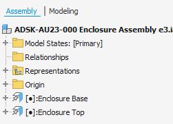
In the model browser, Change the node name of ADSK-AU23-001 Enclosure Base e3-01:1 to Enclosure Base.
Repeat this for ADSK-AU23-002 Enclosure Top e3-01:1, renaming it Enclosure Top.
Write an iLogic rule to pass parameter values from the assembly to the parts.
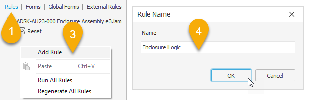
From the iLogic browser, LMB click the Rules’ tab.
In the iLogic panel, find an empty space and RMB click.
Choose Add Rule from the flyout.
The Rule name dialog will open. Type ‘Enclosure iLogic’ into the input box, and LMB click the OK button to create your rule.
The iLogic rule editor will open.
In this tutorial, I’m aiming to get you started with iLogic as quickly as possible – so I’m not going to explain the iLogic editor in depth; we’ll learn more about the iLogic Rule editor is for as we go along.
Copy and paste the following code from this blog post into the code area of the iLogic rule editor:
The lines beginning with an apostrophe ‘ are comments to remind us what this rule does.
The first four lines of code pass the values for the ‘Width,’ ‘Depth,’ ‘Height,’ and ‘Connector’ user parameters from the Assembly User parameters to the ‘Enclosure Base’ User parameters.
The second three lines of code pass the user parameter values from the assembly to the Enclosure top.
The final line of code is the equivalent to clicking the update button from the Inventor user interface (The button with an icon that looks like a flash of lighting).
Test the iLogic code!
This iLogic code takes the value of the assembly-level parameter and ‘pushes’ the parameter’s value down into the matching parameter of the part files.
In the assembly, open the parameters manager.
In the parameters manager, change the value of the Width parameter to 150mm.
In the graphics window, watch the assembly change size… say ‘Oooooo!’.
When the value of the parameter in the assembly changes, the value in the part will also change.
This is true ‘top-down’ control of an assembly, and it can only be accomplished with iLogic.
The code reads:
Find the part with the model browser node name “Enclosure Base”. In this part, find the user parameter named “Width”.
Make the value of the part user parameter “Width” the same as the value of the user parameter in this assembly, also called “Width”.
Next, do the same for the part called “Enclosure top”.
Tip: iLogic forms and rules are typically saved in the file you are working in, meaning the changes you’ve made aren’t saved until you save the open file. When working on your own iLogic projects, save your files regularly to save the changes to your iLogic Rules and Forms—or explore external Rules.
That was fun! What can I learn about iLogic next?
Coming soon: how to use Autodesk Inventor iLogic to configure assembly models.
How can I find out more about Inventor iLogic?
AU (Autodesk University) is Autodesk’s flagship customer event, but the learning doesn’t stop when the in-person event is over. On AU Online, you can find on-demand class videos, handouts, and data sets, so you can enjoy learning from industry experts, partners, and your peers the whole year round—it’s all free, no log-in required.
To help you find the product design and engineering content you need, we’ve created a landing page that curates design and engineering content from AU specifically for you.
Five Autodesk Inventor iLogic productivity hacks for non-programmers: Configurations
Configurations in Autodesk Inventor are an awesome design workflow. They can help standardize and optimize your process, from library parts and assemblies to defeaturing designs for data exchange to the creation of design variants.
If you haven’t used Model states to configure your designs in Inventor before, check them out–they are awesome!
So, why would you use iLogic as a configuration tool? In the past, we used iLogic to compensate for the limits of iParts and iAssemblies. Model states have now overcome many of those limits, and I recommend using Model states for your day-to-day needs.
I recommend iLogic when you are building configurators that may have infinite variations that aren’t easily captured in a model state table.
A more pragmatic reason is that configurable designs are easier to ‘debug’ if I use one method to build them rather than mixing and matching different workflows such as iComponents, Model states, and iLogic.
An interesting note on how iLogic configurations work is that components that aren’t required are removed from the design rather than suppressed, so alternative components don’t appear in the BOM.
In this post, we will see how to use iLogic to add and remove components from an assembly based on a parameter’s value.
When using iLogic to configure assemblies. I prefer to build the assembly first, including all constraints and all options, before adding iLogic. This way, the iLogic rule engine will capture the design intent, meaning less code writing for us.
The dataset was prepared for this exercise, and a basic iLogic rule was created.
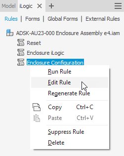
Hover your cursor over the ‘Enclosure Configuration’ rule, RMB click, and choose Edit Rule from the flyout.
The Rule editor will open. Note that an ‘If’ statement and some comments have already been added. For the purposes of this blog post, delete them and copy and paste this code into the iLogic rule editor.
Download the class handout for details on how the code is created automagically using the iLogic rule editor.
‘Monitor the
‘Configuration’ User Parameter
‘If the value of
the Configuration parameter is ‘BLUE’
‘Update the newly
inserted parts to match the assembly parameters
iLogicVb.RunRule("Enclosure iLogic")
‘Update the
document
InventorVb.DocumentUpdate()
In longhand, this rule says:
Watch the user parameter called ‘Configuration’. If its value changes, immediately do the following.
If the value changes to “BLUE”, then, add the Blue enclosure .ipt, including all constraints, and remove the Green enclosure .ipt
If the value changes to “GREEN”, then, add the Green enclosure .ipt, including all constraints, and remove the Blue enclosure .ipt
Then, update the assembly (the same as clicking the Update Button ‘Lightning’).
What does this line of iLogic code do?
‘Update the newly
inserted parts to match the assembly parameters
iLogicVb.RunRule("Enclosure iLogic")
This line of code runs the iLogic rule called ‘Enclosure logic.’ The ‘Enclosure Logic’ Rule maps the values of the Assembly level parameters, down to the part level parameters. This allows us to simultaneously change the dimensions of all the parts, also called ‘Top Down’ editing (click here for more information on top-down design with iLogic).
Why do we need to run this iLogic rule now?
When components are removed from the assembly, they won’t be updated by the ‘Enclosure Logic’ rule. The assembly level parameter values may have changed, and the removed component will be out of date.
Running the ‘Enclosure Logic’ rule now updates the newly inserted component to ensure its parameter values match the assembly-level parameter values.
Testing the iLogic Rule
In the parameters manager, user parameter section, find the Configuration parameter, and from the drop-down list, change the value from “BLUE” to “GREEN”, and back.
You should see the enclosure lid change from the blue design to the green design and back.
Note that the constraints for each component are also deleted or added as the parameter value changes.
Tip: iLogic forms and rules are typically saved in the file you are working in, meaning the changes you’ve made aren’t saved until you save the open file. When working on your own iLogic projects, save your files regularly to save the changes to your iLogic Rules and Forms—or explore external Rules.
That was fun! What can I learn about iLogic next?
Coming soon: how to use Autodesk Inventor iLogic form to standardize completion of a drawing’s title block.
How can I find out more about Inventor iLogic?
AU (Autodesk University) is Autodesk’s flagship customer event, but the learning doesn’t stop when the in-person event is over. On AU Online, you can find on-demand class videos, handouts, and data sets, so you can enjoy learning from industry experts, partners, and your peers the whole year round—it’s all free, no log-in required.
To help you find the product design and engineering content you need, we’ve created a landing page that curates design and engineering content from AU specifically for you.
Five Autodesk Inventor iLogic productivity hacks for non-programmers: Drawing title block form.
One task that has always bugged me is filling out the title block. What do I need to edit? Field text? iProperties? iProperties of the drawing? Or iProperties of the model?
Please tell me what information I need to add, and where I need to add it!
We can make this a lot easier, by creating an iLogic form which collates all the inputs in one place.
In this exercise, we’ll see how we can use an iLogic form to standardize the process for filling out title blocks.
Creating an iLogic form to populate a drawing title block.
An Autodesk Inventor iLogic form can be a great tool to ensure that your team conforms with your drawing and data standards— without the need to read your CAD manual!
By creating an iLogic form, you are making it easy to comply with the CAD standard automatically.
To create the form: In your Inventor template DWG or IDW
Navigate to the iLogic browser, Forms tab.
Hover your cursor over any free space, and RMB click.
LMB click into the form builder cell for Form 1. Enter TITLE BLOCK. This will change the form name.
On the left-hand side of the form editor, under ‘parameters’, find Drawing_Status.
LMB click-and-drag the Drawing_Status user parameter into the form builder area
In the form builder area, in the cell for ‘Label’, to the left of Drawing_status, enter DRAWING STATUS. This will change the label on the form.
With DRAWING STATUS selected, browse the properties. Under Behaviour find Edit control type.
LMB click on ‘Combo box’, from the drop-down menu, choose Radio Group.
Use the data from the table below to add the remaining controls:
NAME
TYPE
SOURCE
PROPERTY
IPROPERTY TAB
NOTES
OWNER
Standard iProperties
Current Drawing
Designer
Project
CREATOR
Standard iProperties
Current Drawing
Author
Summary
CREATION DATE
Standard iProperties
Current Drawing
Creation date
Project
APPROVER
Standard iProperties
Current Drawing
Eng. Approved by
Status
APPROVER DATE
Standard iProperties
Current Drawing
Eng. Approved date
Status
SIZE
Sheet Properties
Current Drawing
Sheet size
n/a
Auto completed
SCALE
Sheet Properties
Current Drawing
Initial view scale
n/a
Auto completed
TITLE
Standard iProperties
Current Drawing
Title
Summary
DECRIPTION
Standard iProperties
Primary or Attached Model
Description
Project
Auto completed (if the data is in the model)
DRG NO
Standard iProperties
Current Drawing
Part number
Project
REV
Standard iProperties
Current Drawing
Revision number
n/a
Controlled by the Revision table
STATUS
Standard iProperties
Current Drawing
Design state
Status
Controlled by an iLogic rule
iLogic title block form controls
To test the form, click the ‘OK’ button in the form editor, then browse to the iLogic panel and click the ‘TITLE BLOCK’ button.
Note how the data updates in the title block when entered into the form. Open the iProperties for the file and see the data you entered into the form.
Making standard procedures easy to follow will increase the likelihood that standards will be followed. Automating a small task like completing a title block can save time and money when you consider how many times a day your users need to update title block information, particularly when you factor in the cost of data not being added or added incorrectly.
How might you implement this workflow at your company? Can you figure out how you might cause the title block form to open automatically if the data is incomplete?
Tip: iLogic forms and rules are typically saved in the file you are working in, meaning the changes you’ve made aren’t saved until you save the open file. When working on your own iLogic projects, save your files regularly to save the changes to your iLogic Rules and Forms—or explore external Rules.
That was fun! What can I learn about iLogic next?
There are five block posts in this series. Have you read them all?
Use iLogic for Assembly configurations [Coming soon].
Use an iLogic form to standardize drawing title blocks [Coming soon].
How can I find out more about Inventor iLogic?
AU (Autodesk University) is Autodesk’s flagship customer event, but the learning doesn’t stop when the in-person event is over. On AU Online, you can find on-demand class videos, handouts, and data sets, so you can enjoy learning from industry experts, partners, and your peers the whole year round—it’s all free, no log-in required.
To help you find the product design and engineering content you need, we’ve created a landing page that curates design and engineering content from AU specifically for you.
Join us for our upcoming webinar on Wednesday, October 2 at 9:00 am (PST) / 12:00 pm (EST), where we’ll dive deeper into Autodesk Informed Design, explore new features, and preview what’s coming next. Register here.
What’s Autodesk Informed Design?
Autodesk Informed Design is a cloud-based solution that connects design and manufacturing workflows to streamline the building design and construction process. Informed Design allows architects to work with customizable, pre-defined building products that help the user yield valid manufacturable results and allow manufacturers to share their products with design stakeholders. Informed Design unlocks industrialized construction – the application of manufacturing principles to the built environment – and will help transform the architecture, engineering, construction and operations (AECO) industry.
Delivering a connected workflow with Autodesk Informed Design
The Autodesk Informed Design offerings are available as follows:
Autodesk Informed Design for Inventor enables product managers and product engineers to align their manufacturing capabilities with customer requirements. This add-in for Inventor provides a more streamlined design and manufacturing process.
Key Capabilities:
Seamless collaboration: Collaborate with designers by creating parametric models of your building products that only allow compliant product configurations to be used.
Powerful Building Information Modeling (BIM) content creation directly in Inventor: Define BIM content to confirm your building products meet project requirements and are compatible with other components and industry standards.
Streamlined product documentation: Simplify the generation of product documentation at scale and generate the necessary outputs for fabrication.
Architects can now effortlessly incorporate your products into their designs by integrating your product dimensions, weights, materials, and other critical information into the Revit environment via the Informed Design for Revit add-in. This collaboration ensures that your products are accurately represented and compliant with project requirements, providing designers with the confidence to design with certainty.
What you can do with Informed Design for Inventor
Author manufacturing constraints
With Informed Design for Inventor, you can define rules visually using code blocks to limit building product customization based on manufacturing capabilities. This ensures that any customizations made to the product remain within your manufacturing processes’ allowable limits.
During the authoring process, you can preview and test the rules to confirm correct parameter validation and model updates in response to edits. This feature helps ensure that all customizations adhere to the defined manufacturing constraints before finalizing the product design.
Preview manufacturing constraint rules
Set output type availability
Define the range of output types that your building product can produce. This allows you to control the available outputs, ensuring that they meet the specific needs of your manufacturing and documentation processes.
Manage work-in-progress versions
Informed Design for Inventor allows you to create multiple product definitions per Product, enabling you to iterate and experiment or release context-specific variations of a manufacturing-constrained product. This flexibility supports the ongoing development and refinement of product designs.
Register to learn more
Join us for our upcoming webinar to learn more about Autodesk Informed Design. Engage directly with our product experts, explore new features and updates, and get an exciting sneak peek at what’s on the horizon.
Great news! Inventor 2025.2 has been released! This update is packed with enhancements for sketching, part modeling, assembly modeling, drawings, Revit interoperability, and several other general enhancements. We’ll cover each of these categories in detail below.
Sketch enhancements
Midpoint line
Use the newly added Midpoint Line command in the 2D sketch environment to create a line symmetrical from its midpoint. Specify the midpoint to start the line. Then, click to set the endpoint of the line, or use the edit field to define its length or angle from the midpoint. Note that a coincident constraint is created between the midpoint and selected geometry.
Double-click to edit non-active sketches
In both 2D and 3D sketches, it is now possible to switch to another sketch in the document without needing to click “Finish Sketch” or “Cancel Sketch.”
Change the direction of sketch patterns when editing
In parts and assemblies, you can now edit the direction of an existing 2D sketch pattern.
3D model courtesy of Mastenbroek
Part modeling enhancements
Sheet metal enhancements
Previously, it was necessary to select corner edges one by one when rounding and chamfering corners using the Corner Round and Corner Chamfer commands. Now, you can use the window select method to select the edges for rounding and chamfering.
3D model courtesy of Mastenbroek
Preview for Combine features
The standard Realistic Preview option is added in the top right corner of the Combine panel. Design results are displayed in the canvas before you click OK. By default, this new preview is enabled.
Sort order for objects
Use the new Sort drop-down to specify the order of the tree nodes including parameters. It is added to the following dialogs:
Export Objects
Derive Part, Derive Assembly
Link Parameters from Parameters dialog
You can specify the list of objects by choosing alphabetically ascending, alphabetically descending, or using the default settings.
Assembly modeling enhancements
Presentation enhancements
In this release of Inventor, the ability to search dependent document iProperties in the IPN file type has been added.
You are now also able to select a desired Model State. Right-click the scene, select Representations from the context menu, and then select the model state.
Model State enhancements
Previously, when a dimension was edited during creation, the initial unedited value was captured in the Model States table for all other model states. Now, Inventor does not treat an initial value change as an edit and will not capture it in the Model States table.
Updated browser icons
The following browser icons were updated to be more easily recognizable and consistent.
Representations
Relationship
Finish
Origin
New zero quantity toggle in bill of materials
The Bill of Materials dialog has been redesigned. Two options to show or hide items with zero quantity are added directly to the toolbar. Use the new Hide/show rows with zero quantity toggle in the toolbar. When active, you can also renumber the order sequentially using the new Automatic re-numbering sequentially toggle.
Tube and Pipe enhancements
Now, all default Bend Radius values are saved into the exported Tube and Pipe style. The bend radius in T&P style can be exported to XML file, and it can also be imported.
Drawing enhancements
Highlight balloons in the parts list
When you select one or more Parts List rows, the corresponding balloons are highlighted. Balloon cross-highlighting helps you easily find the balloons corresponding to the selected parts list row, making it easier to locate the ballooned part geometry.
Component selection to cross highlight in parts list row
Starting with this release, when you select a geometry, the corresponding Parts List row is highlighted (make sure the “Select Part Priority” selection filter is active). This functionality also applies to browser selection.
3D model courtesy of Mastenbroek
Selection of component pattern
It is now possible to select the component pattern in the drawing browser. Selecting a component pattern highlights the browser entry for the pattern (only) and all components in the graphics that make up that pattern (or pattern of patterns). Additionally, the Visibility and Select Edges options were added to the context menu.
Show hidden edges preview in Break Out view
The Break Out dialog has been redesigned to better suit workflows making it easier to use and more intuitive.
The changes include:
Hidden Edges control is moved inside the Depth area
Hidden Edges control is active only when the view has hidden lines removed
Revit interoperability
New AEC properties access
The AEC Properties command is now added to the Inspect tab in the ribbon for assemblies, allowing you to easily view the imported Properties of IFC files. Note that this command is always enabled for any assembly. When launched, live selection becomes active, and any IFC properties will display for a selected component. If no properties are available, the message “No properties to display” appears.
Open future Revit files in Inventor
Starting with this release, Inventor will support opening future Revit files. This functionality will be realized when Revit 2026 is released.
General enhancements
Quick color scheme and background change
In the part, assembly, and presentation environments, you can now temporarily override the color scheme and background color. Go to the View tab, expand Appearance, and select the desired color scheme and background color type.
3D model courtesy of Mastenbroek
Support display separate colors in express mode
In Express Mode, you can now use Display Separate Colors without needing to load the full assembly. Note that only the For Each Top-Level Component and For Each Part options are supported. The other two options still require loading the Load Full option.
3D model courtesy of Mastenbroek
Display separate colors for meshed parts
Display Separate Colors functionality is now available for meshed parts.
Visually differentiate between transparent and inactive components in the canvas
Transparent components now render with edges by default, making them visually distinct from inactive components when viewed in the canvas. The visual style for both inactive and transparent components can be customized independently on the Display tab of the Application Options. Specify the options in the Inactive and Background Component Appearance and Transparent Component Appearance areas of the dialog.
Additional controls for rendering edges of transparent and inactive components are now available. These include options for following edge visibility with different visual styles and using the normal edge color rather than just a fixed one.
3D model courtesy of Mastenbroek
Access to the template location
Access to template files is now easier using the Create New File dialog. The following two options are added to the top right corner:
Copy Path: Copies the path of the selected file to the clipboard.
Open Location File Explorer to the specified path. This path is always set according to the settings in Application Options > File tab > Default templates.
Update home Vault status
Inventor Home now automatically updates the status of any Vault file (for example, the file is checked in/out, the local file is modified, etc.). Previously, a manual refresh was required to display the most recent status.
Updates to Style Library Manager list controls
In the Style Library Manager, styles with long names now have a horizontal scroll bar for ease of readability. Additionally, tooltips have been added to all styles.
Happy New Year! As we transition into the year 2025, we would like to reflect on a great year of enhancements for Autodesk Inventor. The development team continues to work hard to include your requests. They released three major updates that included 150 enhancements based on your feedback. Thank you for your effort and contributions to helping to make Inventor the best it can be for your most important design work. We received thousands of votes to drive the focused areas for each release. Your votes play a significant role, not only in each enhancement but also in maintaining the highest level of stability so you can focus on your designs without disruption.
Inventor 2025 Feature Highlights
Let’s look at some notable enhancements you saw this year. To see a complete list of enhancements, visit the online help guide or watch our video demonstrations on YouTube.
Sheet metal
Inventor 2025 introduced a modernized interface for designing sheet metal components, making the process more intuitive and efficient than ever before. The new UI streamlines design workflow by placing tools in a logical order and making previously hard-to-find features readily accessible.
Part modeling
Let’s take a look at part modeling enhancements. Starting with boundary options for patterning. If your pattern crosses a selected sketch boundary, you can specify to omit those instances.
There are three new options
Only accept instances within the boundary
Keep them if the centroid is inside the boundary
Or if the base points are inside the boundary
These options are also available for sketch-based patterns.
You may remember the Finish feature was new last year for Inventor 2024. This year there were several enhancements added.
Include and exclude selectors were added for ease of use. Switch between solid body, surface body, or faces for selection. And if you’re using “Make Part”, your finish features will show in the derived part.
And you will also find an option to show extended names in the browser. For example, you may want it to display the following.
Material coating
Heat treatment
Surface texture
Paint
Assembly modeling
While using the simplify command, you can select bounding boxes or cylinders for your components. This is great for creating a highly simplified envelope for complex parts in your assemblies. It will reduce the amount of memory needed to work on very large designs.
How do you color your parts in your subassemblies? What sort of standard are you using for colors? We know that color can make it easier to find parts or understand the assembly better. Now in 2025, you can quickly change the color of everything temporarily.
Select from the following options to automatically change color:
Individual parts
Unique parts of the same color
Top-level subassemblies
Unique top-level subassemblies of the same color
And there is the option to customize the colors that are used. You will find this in the color scheme editor in the application options.
Drawings
There are a lot of enhancements to talk about for annotations. You can use presets in general notes for text, symbols, and parameters.
You can also add background color fill to drawing dimensions. This may improve the readability of dimensions on a background color. Note that the background fill is supported when exporting to DWG.
If you are creating parts lists, then you can add parts list properties from selected parts to the text dialog.
Some of you are using revision cloud arc which was new last year. You can now edit the size of the cloud arcs around smaller details in the view. There is also an option to edit the revision cloud as you create them for quick changes.
Diameter and radius dimensions now have the option to hide the extension line.
Right-click on the dimension to find the setting. And if you are creating tables in your drawings then you will find a new option to merge cells.
There are several enhancements in the drawing styles editor. Inventor continues to see updates for ISO standards. Standards for arc symbols and surface texture have been addressed in this release.
You will find a new option for revision tables. You can now set the default to alpha or numeric. And there’s a new option in the styles editor for BOM sort order. Change the sort settings for primary, secondary, and tertiary columns along with an “auto sort on update” checkbox.
Finally, crop views have been added to styles to set the preferences for break lines and symbols.
Interoperability
We’ve enhanced the interoperability of our software ecosystem with significant improvements to import and export functionality. The major reveal is the IFC import feature, which allows for robust handling of assemblies, either by referencing or converting them. Additionally, the RFA export has been optimized to offer greater graphical fidelity, ensuring high-quality visuals in exported models.
Also, some notes on Revit & BIM specifically. We’ve added the ability to import Revit Models going back as far as 2023 as well as updated the simplify command and added a new prompt to install the necessary version of Revit.
Informed Design for Inventor
The Informed Design workflow for Inventor and Revit enhances design interoperability by enabling manufacturers to author and publish customizable building products, components, or assemblies.
Designers can then access, customize, and incorporate these designs into the Revit environment files, adhering to any predefined constraints.
A bi-product of the workflow is the automatic generation of manufacturing documentation in the web portal.
Customer focused webinars
We have conducted dozens of webinars this year for design and manufacturing solutions. Be on the lookout for more customer-focused webinars as we head into next year. See this webinar where we partnered with Woodway to discuss how they automate their design and engineering processes.
Looking forward to a bright 2025
Thank you to our wonderful community of Inventor users who influence the future of how your products get designed and manufactured successfully. Continue to communicate your ideas to us and to the rest of the user community. We look forward to 2025 as we collaborate with you to tackle your biggest challenges.
Explore how Inventor iLogic can help you get more done and how to get started
Overall, iLogic enhances the capabilities of Autodesk Inventor, making it a powerful tool for improving design quality, consistency, and productivity. Key benefits include:
Automation: iLogic allows you to automate repetitive tasks, saving time and reducing the potential for errors. For example, you can create rules to automatically update iProperties, replace components in assemblies, or update text blocks in drawings.
Consistency: By using iLogic, you can ensure that your designs follow consistent standards and rules. This is particularly useful for maintaining uniformity across large projects or multiple team members.
Efficiency: iLogic can streamline your workflow by automating complex tasks that would otherwise require manual intervention. This can include updating parameters, suppressing features, or changing component configurations based on specific conditions.
Flexibility: iLogic provides a way to add intelligence to your designs. You can create rules that respond to changes in parameters, model geometry, or drawing views, making your designs more adaptable and responsive to different scenarios.
Ease of Use: iLogic simplifies the process of writing automation rules by providing a user-friendly interface and pre-built code snippets. This makes it accessible even to those who may not have extensive programming experience.
How to get started using iLogic
There are lots of great resources available, here are a few we recommend to help you get started using iLogic.
It’s time to announce another great release for Autodesk Inventor! Discover over 140 enhancements to help you solve your everyday design challenges. Each of them are carefully crafted to improve user experience, enhance functionality, and streamline design processes.
Check out the following video demonstrations for some of the highlights for this release. If you want to learn more and ask questions to the experts, then be sure to register for the upcoming webinars listed at the end of the article.
Inventor 2026 highlights
Associative mirror
Mirroring and editing your assemblies is faster and easier than ever. Any changes you make to the source component position or geometry are reflected and remain associative on the mirrored side.
Sheet Metal
The sheet metal interface continues to see modernized improvements to features like the contour flange, corner round, and punch tool. This provides a more streamlined workflow that includes direct manipulation in the graphics area.
Patterning
Patterning features has also seen modernization improvements for rectangular, circular, and sketch driven. All three of these pattern features have been moved to the property panel and include a new shaded preview and graphic manipulation. Brand new to the rectangular and circular patterns is irregular spacing. Choose specific instances from the graphics view and specify any value.
Simplify parts
The simplify command can now be accessed in the part environment from the 3D model tab in the Simplification panel. Quickly exclude bodies by size, remove features, or replace bodies with envelopes.
Revit interoperability
Interoperability with Revit data has seen several enhancements for this release. New commands have been added in the BIM Content Environment. The UCS and Placement commands assist in the proper orientation and location of your assets. There are also new commands to include properties and simplify your data for export. And quickly include Revit Categories to your parts and assemblies from the iProperties dialog or in the Bill of Material interface.
Break view
There is a new Break View workflow that enables more control of your break lines. You can now place your break lines in a sketch and dimension the distance to entities within the view. The sketch is stored in the browser for future editing when needed.
Register to learn more
In this release of Inventor, we have continued our commitment to provide tools to streamline your design process, improve your experience, and remove boundaries for seamless interoperability. Our goal is to equip you with the most advanced tools to help you get your designs to manufacturing as quickly as possible.
The videos above are only a portion of the enhancements for this release. Be sure to register for our upcoming webinar series to learn more about Inventor 2026 and ask questions to our experts. We have three webinars based on your region. The link to the May 20 webinar will be coming soon.